|

| Quantity: | |
|---|---|
HPBL3000
ZHIBI
Summary
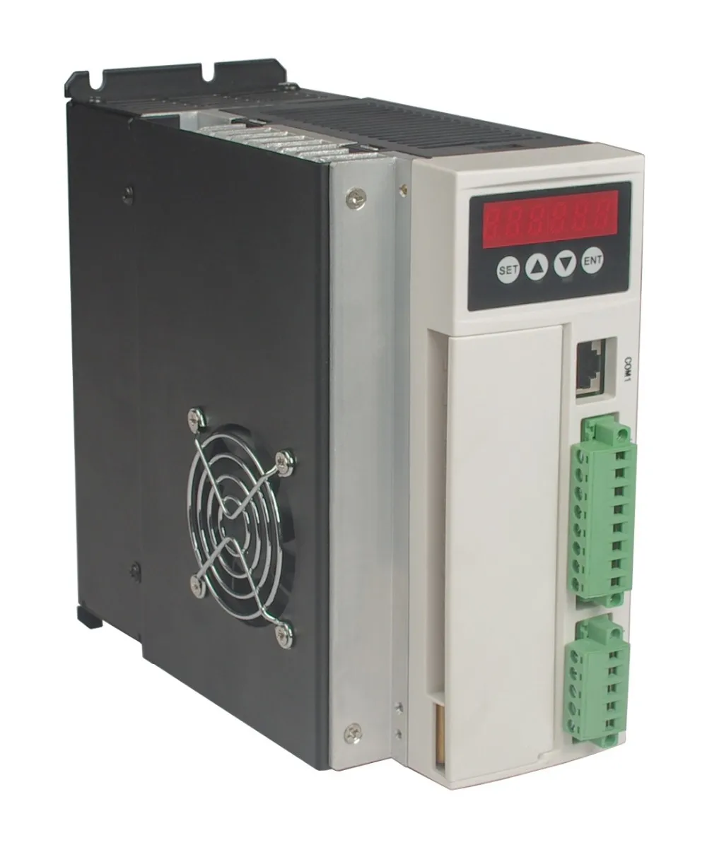
220VAC BL drives is a powerful driver designed by zhibi Technology independence which is assorted with the advanced motion control industrial. The drives adopt the latest DSP specialized for motor as the core technical matched with high speed digital logic chips and high quality power module. It gets the advantage on highly integration, small volume, well protection, high reliability etc. This drives can provide: panel speed adjust command, external simulative voltage, external potentiometer, pulse width speed adjust etc.
The main function of the drive is as follows:
●Choose a variety of speed adjustable, including input voltage setting, drive's internal speed setting,
communication interface setting etc.
●Complete isolation of electric supply, and Hall signal interface, guarantee of security.
●Digital display panel, abundant display content settings, abundant feature setting.
●The drive device of automatic protection, automatic control of current, with undervoltage and overvoltage, blocking and hall fault lamp protection function.
●The standard series can provide 2 times or even higher short-term overload current, different products with different supply.
Product features:
1. System Characteristic
Input Voltage: 110/220/380VAC, 50/60Hz
Continuous Output current: 12A
Max. Output current: 30A
Working temp.: 0~+45°C
Storage temp.: -20~+85°C
Working & storage humidity: <85% no frosting
Structure: wall-mountable box type
Dimension:L180 x W85 x H190mm
2. Basic Characteristic
Cooling: Radiator
Control terminals: Isolation
Protection: Over load, over heat, over speed, over voltage, lost voltage will cause the power abnormity
Panel: 6 digit LED display, 4 digit keypad operation
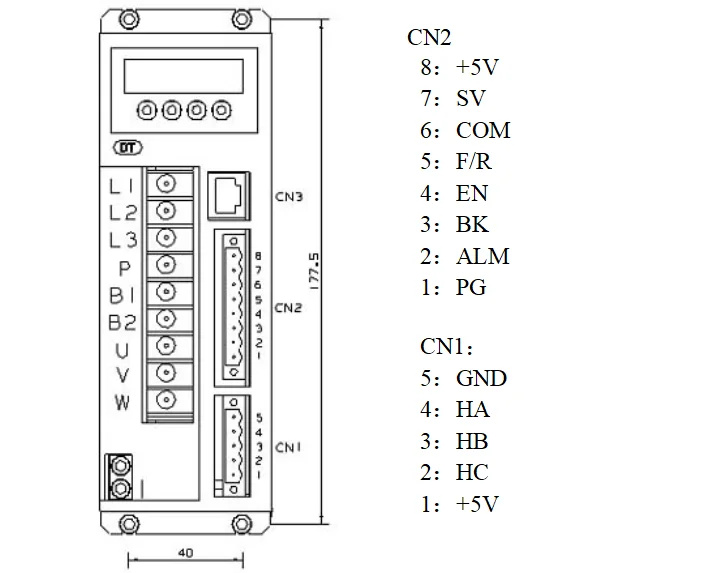
Terminal Function Specification
3) Parameters setup
3.1 Parameters P1
This series characteristics are used to set up some functions by clients self, they can be self-adjust according to clients' different demand. They are operation functions, have no relation with fundamental characteristics of driver.
Parameter P1
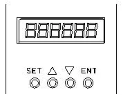
3.2 Control Panel Operation
Display instruction: total 6 digital tube shows "888888", the light most is the first and the lowest.
As picture on left, there are 4 keys on the panel,
"SET": press this key can enter or quite P1 setup menu
"▲"and "▼": "+"and "-",to choose the function and adjust the parameters.
"ENT": "confirmation" and "operation", when setting parameters, press this button to enter adjustment interface and jump. Under trial operation type, press ENT to start or stop motor.
Attention: The adjustment is forbidden if the adjusted value is larger than the maximum allowed, the bottom will be no response.
How to set parameters
Example:
Demand: set internal speed (P1.1) to 1000rpm/min
Operation step as below:
1.After connecting with power, display "H 0", the driver is standby, press "SET", will display"P0. 0", press "▲"until displayed "P0.6", press "ENT", display"00000", and the first of light most is flashing, press" ▲", change into "1", press "SET", display "P0. 6" . This step is to complete the P1 parameter set to unlock
2. Press "SET", display "P1 0", the driver is entering P1 setting state
3.Press "▲", until display "P1. 1"
4. Press "ENT", display "2000", and the first of light most is flashing
5. Press "ENT", until the flashing is moving to the fourth position
6. Press "▼", change into "1000"
7. Press "SET", display "P1. 1", the parameters had been set up and save automatic
8. Press "SET" again, back to standby state, display "H 0". Now, the new parameters adjustment had finished and take effect
Attention: 1. after adjustment, the driver need to connect with power again, then the new parameters will take effect
2. The parameters with "★" in the list can not been adjust when motor working
3. The adjustment is forbidden if the adjusted value is larger than the maximum allowed, the bottom be will no response
Summary
220VAC BL drives is a powerful driver designed by zhibi Technology independence which is assorted with the advanced motion control industrial. The drives adopt the latest DSP specialized for motor as the core technical matched with high speed digital logic chips and high quality power module. It gets the advantage on highly integration, small volume, well protection, high reliability etc. This drives can provide: panel speed adjust command, external simulative voltage, external potentiometer, pulse width speed adjust etc.
The main function of the drive is as follows:
●Choose a variety of speed adjustable, including input voltage setting, drive's internal speed setting,
communication interface setting etc.
●Complete isolation of electric supply, and Hall signal interface, guarantee of security.
●Digital display panel, abundant display content settings, abundant feature setting.
●The drive device of automatic protection, automatic control of current, with undervoltage and overvoltage, blocking and hall fault lamp protection function.
●The standard series can provide 2 times or even higher short-term overload current, different products with different supply.
Product features:
1. System Characteristic
Input Voltage: 110/220/380VAC, 50/60Hz
Continuous Output current: 12A
Max. Output current: 30A
Working temp.: 0~+45°C
Storage temp.: -20~+85°C
Working & storage humidity: <85% no frosting
Structure: wall-mountable box type
Dimension:L180 x W85 x H190mm
2. Basic Characteristic
Cooling: Radiator
Control terminals: Isolation
Protection: Over load, over heat, over speed, over voltage, lost voltage will cause the power abnormity
Panel: 6 digit LED display, 4 digit keypad operation
Terminal Function Specification
3) Parameters setup
3.1 Parameters P1
This series characteristics are used to set up some functions by clients self, they can be self-adjust according to clients' different demand. They are operation functions, have no relation with fundamental characteristics of driver.
Parameter P1
3.2 Control Panel Operation
Display instruction: total 6 digital tube shows "888888", the light most is the first and the lowest.
As picture on left, there are 4 keys on the panel,
"SET": press this key can enter or quite P1 setup menu
"▲"and "▼": "+"and "-",to choose the function and adjust the parameters.
"ENT": "confirmation" and "operation", when setting parameters, press this button to enter adjustment interface and jump. Under trial operation type, press ENT to start or stop motor.
Attention: The adjustment is forbidden if the adjusted value is larger than the maximum allowed, the bottom will be no response.
How to set parameters
Example:
Demand: set internal speed (P1.1) to 1000rpm/min
Operation step as below:
1.After connecting with power, display "H 0", the driver is standby, press "SET", will display"P0. 0", press "▲"until displayed "P0.6", press "ENT", display"00000", and the first of light most is flashing, press" ▲", change into "1", press "SET", display "P0. 6" . This step is to complete the P1 parameter set to unlock
2. Press "SET", display "P1 0", the driver is entering P1 setting state
3.Press "▲", until display "P1. 1"
4. Press "ENT", display "2000", and the first of light most is flashing
5. Press "ENT", until the flashing is moving to the fourth position
6. Press "▼", change into "1000"
7. Press "SET", display "P1. 1", the parameters had been set up and save automatic
8. Press "SET" again, back to standby state, display "H 0". Now, the new parameters adjustment had finished and take effect
Attention: 1. after adjustment, the driver need to connect with power again, then the new parameters will take effect
2. The parameters with "★" in the list can not been adjust when motor working
3. The adjustment is forbidden if the adjusted value is larger than the maximum allowed, the bottom be will no response