
As picture on left, there are 4 keys on the panel,
"R/S": ON/OFF
"+": Plus 1
"-": Minus 1
"⬅I": "ENTER" Confirm setting parameter
 |

| Quantity: | |
|---|---|
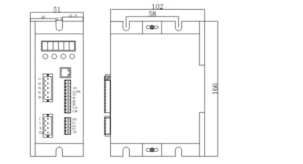
DBLS-07-S
Summary
DBLS-07-S BLDC motor driver is designed by Zhibi Technology independence which is assorted with the advanced motion control industrial. It is suitable for BLDC motor with the power under 400W. The driver adopts the latest high performance digital logic chips specialized for brushless motors, has the advantage on high integration, small volume, well protection, high reliability etc. The driver uses a new type of PWM technology that enable the motor running high speed, small vibration, low noise, good stability and high reliability.
Product Characteristic
1. System Characteristic:
Input Voltage: AC85~265VAC, 50/60Hz,
Continuous Output current:3.5A (AC), Suitable for ≤750W motor
Working temp.: 0~+45°C Storage temp.:-20~+85°C
Working & storage humidity: <85% (no frosting)
Structure: wall-mountable box type
2. Basic Characteristic
Cooling: Radiator
Control terminals: Isolation
Work mode: speed open loop, speed closed loop, external interface control, panel manual control,
sense mode, no sense mode, external analog voltage speed regulation, external PWM signal speed
regulation, speed display, current effective value display, maintenance mode.
Protection:Over load, over heat, over speed, over voltage, lost voltage will cause the power abnormity.
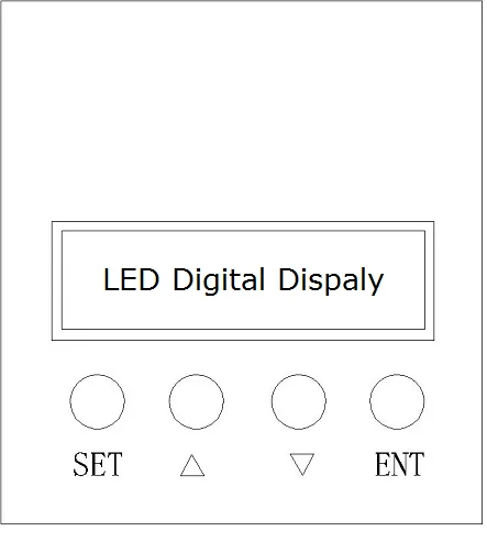
Panel:6 digit LED display, 4 digit keypad operation
Panel Operation
Display instruction: total 6 digital tube shows "888888", the light most is the first and the lowest.
As picture on left, there are 4 keys on the panel,
"R/S": ON/OFF
"+": Plus 1
"-": Minus 1
"⬅I": "ENTER" Confirm setting parameter
Summary
DBLS-07-S BLDC motor driver is designed by Zhibi Technology independence which is assorted with the advanced motion control industrial. It is suitable for BLDC motor with the power under 400W. The driver adopts the latest high performance digital logic chips specialized for brushless motors, has the advantage on high integration, small volume, well protection, high reliability etc. The driver uses a new type of PWM technology that enable the motor running high speed, small vibration, low noise, good stability and high reliability.
Product Characteristic
1. System Characteristic:
Input Voltage: AC85~265VAC, 50/60Hz,
Continuous Output current:3.5A (AC), Suitable for ≤750W motor
Working temp.: 0~+45°C Storage temp.:-20~+85°C
Working & storage humidity: <85% (no frosting)
Structure: wall-mountable box type
2. Basic Characteristic
Cooling: Radiator
Control terminals: Isolation
Work mode: speed open loop, speed closed loop, external interface control, panel manual control,
sense mode, no sense mode, external analog voltage speed regulation, external PWM signal speed
regulation, speed display, current effective value display, maintenance mode.
Protection:Over load, over heat, over speed, over voltage, lost voltage will cause the power abnormity.
Panel:6 digit LED display, 4 digit keypad operation
Panel Operation
Display instruction: total 6 digital tube shows "888888", the light most is the first and the lowest.
As picture on left, there are 4 keys on the panel,
"R/S": ON/OFF
"+": Plus 1
"-": Minus 1
"⬅I": "ENTER" Confirm setting parameter